Vt Commodore Ignition Wiring Diagram, Complete Wiring Diagrams For Holden Commodore VT, VX, VY, VZ, VE, VF, 5.36 MB, 03:54, 32,796, John Amahle, 2018-08-01T19:37:41.000000Z, 19, Vt Commodore Ignition Wiring Diagram, to-ja-to-ty-to-my-to-nasz-swiat.blogspot.com, 1272 x 1800, jpeg, bcm pcm 12j swiat nasz, 20, vt-commodore-ignition-wiring-diagram, Anime Arts
All technical data sheets can be downloaded. To view these files you will need an adobe acrobat reader which can be downloaded free from the link below. 1. 4. 3 block diagram of the frequency converter illustration 1. 3 is a block diagram of the internal components of the frequency converter. See table 1. 2 for their functions.
Fuses and circuit breakers. danfoss’ global support organization is geared to react swiftly to resolve issues to help you reduce downtime. See table 12 for their functions. The diagrams below show typical wiring circuits with which the wiring conversionsto be used when. Wiring diagrams and further information continues below. Danfoss hpa2 valve wiring diagram the h series motorised valves, working in conjunction with time controls and thermostats,are used in domestic and commercial central heating, hot water and chilled water systems to control the fl ow of water in the system. Thermostat service kit for danfoss part# 077f1555; Thermostat service kit for danfoss part# 077f1555 thermostat service kit for danfoss part# 077f1555 manufacturer: $262. 57 be the first to review this product. 120v/60hz, with knob and bezel.
23+ Danfoss 077F1555 Wiring Diagram Images | markmatsose

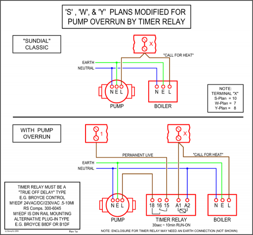
Danfoss S Plan Wiring Diagram

Danfoss S Plan Wiring Diagram

Screen Shot 2016-10-27 At 20.56.15 | DIYnot Forums

Danfoss Pressure Transmitter Wiring Diagram

Danfoss Vfd Wiring Diagram - OUCAHM

Danfoss Thermostat Wiring Diagram

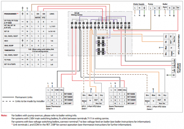
Danfoss Zone Valve Wiring Diagram - 15

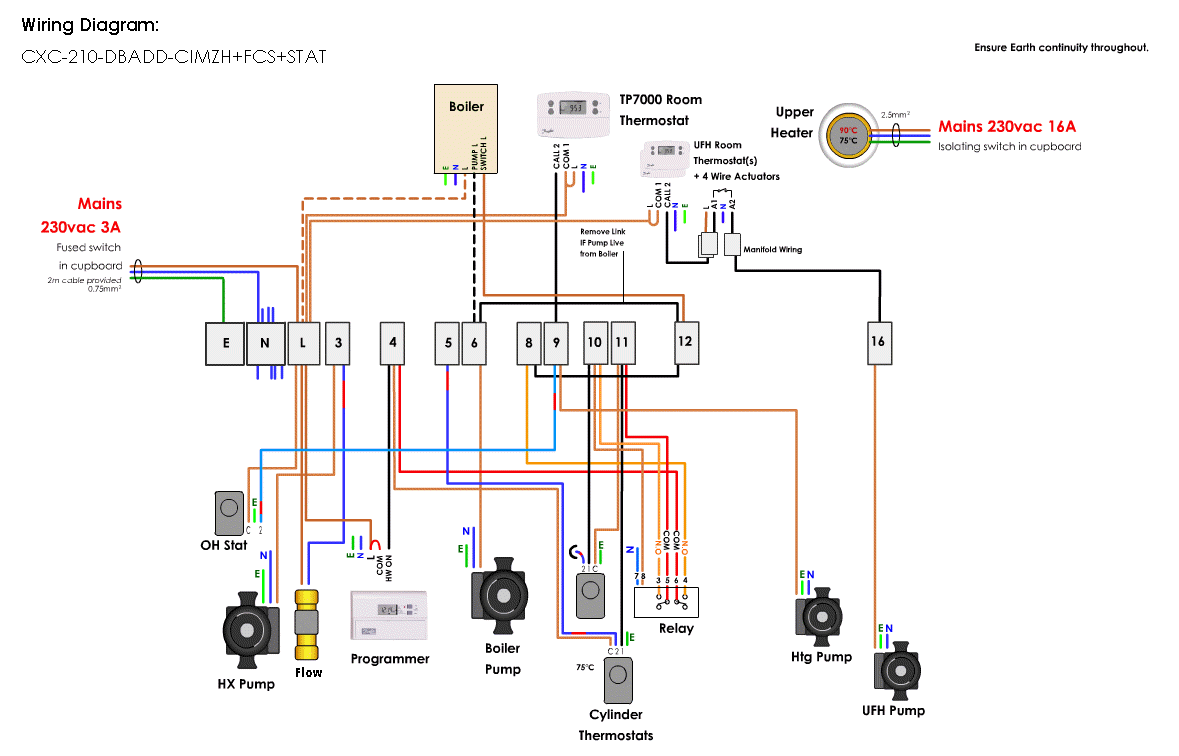
Central Heating Wiring Diagrams - Danfoss 3 Port Mid Position Wireless Stats - Gas Support Services

Danfoss 3 Way Valve Wiring Diagram - yazminahmed

