Vt Commodore Ignition Wiring Diagram, Complete Wiring Diagrams For Holden Commodore VT, VX, VY, VZ, VE, VF, 5.36 MB, 03:54, 32,796, John Amahle, 2018-08-01T19:37:41.000000Z, 19, Vt Commodore Ignition Wiring Diagram, to-ja-to-ty-to-my-to-nasz-swiat.blogspot.com, 1272 x 1800, jpeg, bcm pcm 12j swiat nasz, 20, vt-commodore-ignition-wiring-diagram, Anime Arts
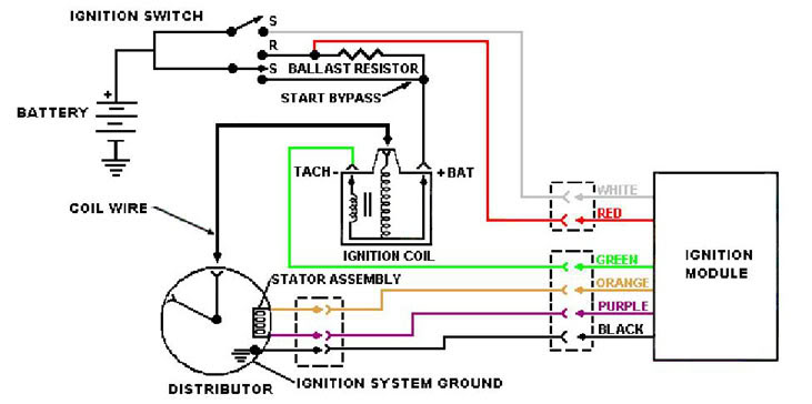
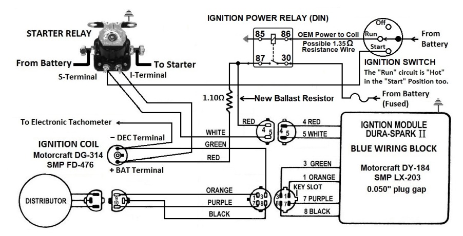
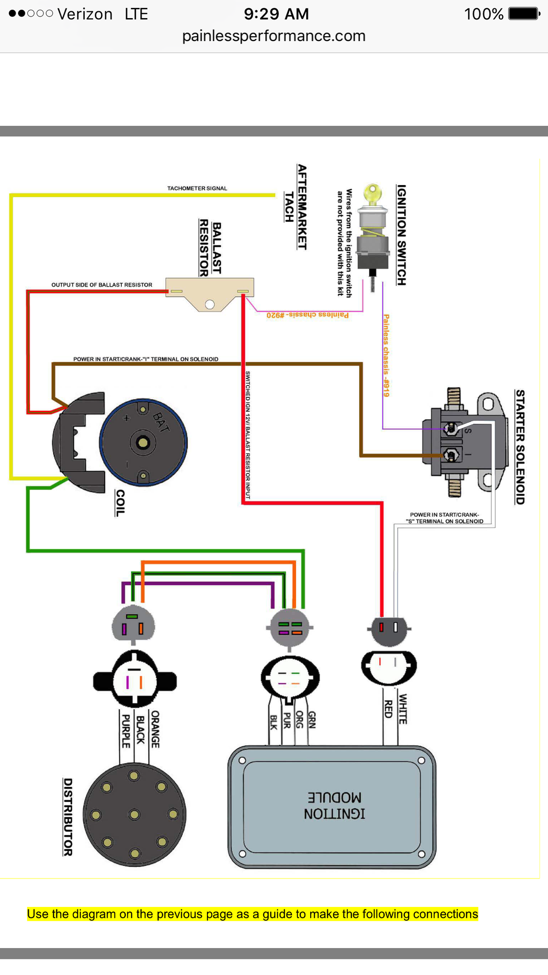
Painless performance duraspark ii distributor wiring harnesses. They feature preterminated wire ends with installed weatherpack connectors for a quick and easy fit. It is, for the most part, a stand alone system needing only one outside power connection. The control box gets its only power through the red wire in the 2 pin connector.
And a solid 12. I am doing a duraspark 2 swap in my 68 289. I am very confused about the wiring of the red and white wires going into the ignition box. Some people choose to replace this ignition with an earlier duraspark ignition. If you don't want to use a duraspark box you can also use the smaller chrysler unit. This schematic is for a single cylinder utility engine, but the same wiring theory applies. If you're using a coil designed for full 12v, omit the resistor. The wire with the black heat shrink at 1 o'clock is the power supply from the relay. The paired wires at 5 o' clock, i have zero idea?
Duraspark II -- The Ford V-8 Engine Workshop
Duraspark II Wiring Question - Ford Muscle Forums : Ford Muscle Cars Tech Forum

Dura Spark II

40 Duraspark 2 Distributor Wiring Diagram - Wiring Diagram Online Source

TWH Download Duraspark Ii Wiring Diagram in ePub
Painless Duraspark ii question - Ford Truck Enthusiasts Forums

Duraspark II conversion for 86 I-6 - Page 4 - Ford Truck Enthusiasts Forums
Duraspark II done but wont turn off? - Ford Mustang Forum
Duraspark 2 Wiring Diagram - 27
41 Duraspark 2 Wiring Diagram - Wiring Diagram Online Source

