Vt Commodore Ignition Wiring Diagram, Complete Wiring Diagrams For Holden Commodore VT, VX, VY, VZ, VE, VF, 5.36 MB, 03:54, 32,796, John Amahle, 2018-08-01T19:37:41.000000Z, 19, Vt Commodore Ignition Wiring Diagram, to-ja-to-ty-to-my-to-nasz-swiat.blogspot.com, 1272 x 1800, jpeg, bcm pcm 12j swiat nasz, 20, vt-commodore-ignition-wiring-diagram, Anime Arts
The modern ev is purpose built, based on original body and frame designs. This satisfies the structure requirements unique to evs and makes use of the greater flexibility of electric propulsion [2] a modern electric drive train consists of three major subsystems: Electric motor propulsion, energy source, and auxiliary. Wire cover power cable (comes with plug version only) installation template for plug version:
Is a diagram of the overall charging energy flow from the power grid, through the evse (shaded in orange) and into the vehicle through the industry standard j1772 port connector. With alternating current (ac) evse, charger electronics within the vehicle invert the ac power supplied by the evse into direct current (dc) for storage in the battery. Ev charging wiring diagram. June 7, 2022 january 11, 2022 by waldo points. Electric vehicle on board chargers and charging stations charger control project greening me ahead with vehicles c3controls j1772 portable ev plug 32a car parts co the hacksmith charge a one wheel at any station block diagram sbd hev level 1 2 electronic products dc fast. There are three wires, shown in the diagram as blue, white, and red. The 240 volts is between the blue and red wire, while 120 volts is between the blue and neutral white wire, and between the red and neutral white wire. These colors are just for illustration, and usually, the real wires are all black or the neutral may be a bare wire. After connecting the positive terminal, you need to turn on the ignition key.
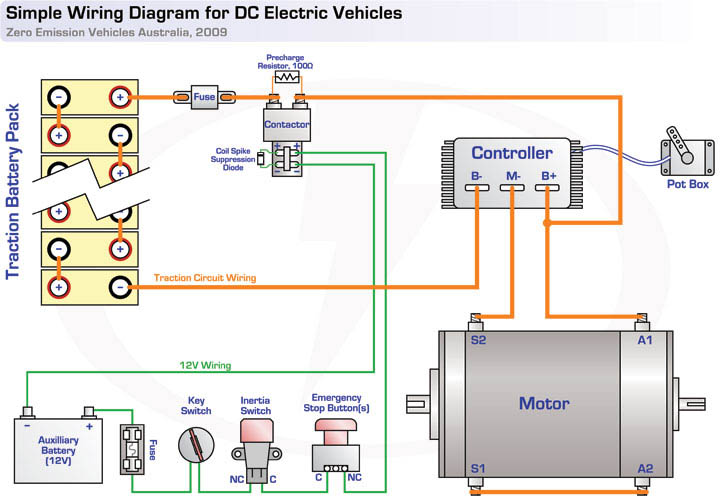
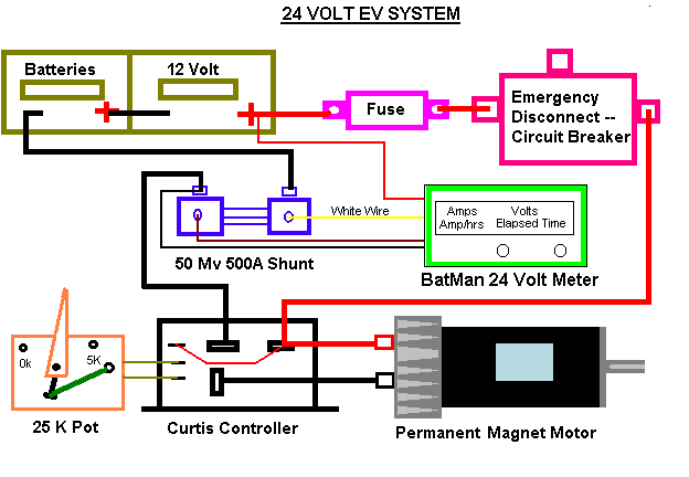
EV Conversion Schematic
Entire EV Wiring Diagram - Questions, Comments | DIY Electric Car Forums
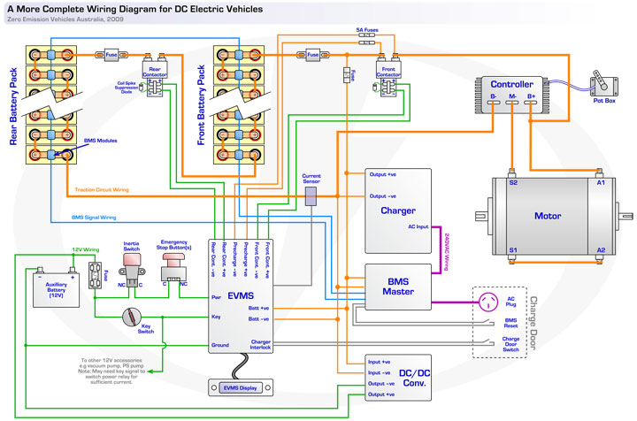
EV Tech info Circuit Diagrams

EV Conversion Schematic
Small Vehicle Wiring Schematic

Electric Vehicle Conversion: Electro: Wiring Diagrams, Take 2

EV Tech info Circuit Diagrams

Polari Ranger Ev Wiring Diagram - Wiring Diagram
Please check my wiring diagram - DIY Electric Car Forums
Wiring Diagram Electric Car Conversion

