Vt Commodore Ignition Wiring Diagram, Complete Wiring Diagrams For Holden Commodore VT, VX, VY, VZ, VE, VF, 5.36 MB, 03:54, 32,796, John Amahle, 2018-08-01T19:37:41.000000Z, 19, Vt Commodore Ignition Wiring Diagram, to-ja-to-ty-to-my-to-nasz-swiat.blogspot.com, 1272 x 1800, jpeg, bcm pcm 12j swiat nasz, 20, vt-commodore-ignition-wiring-diagram, Anime Arts
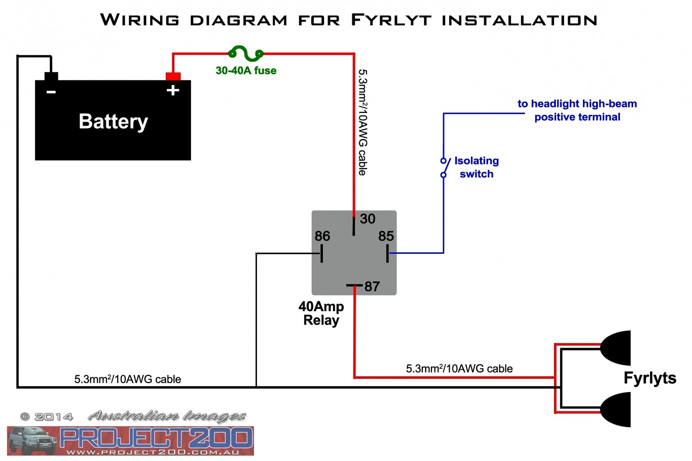
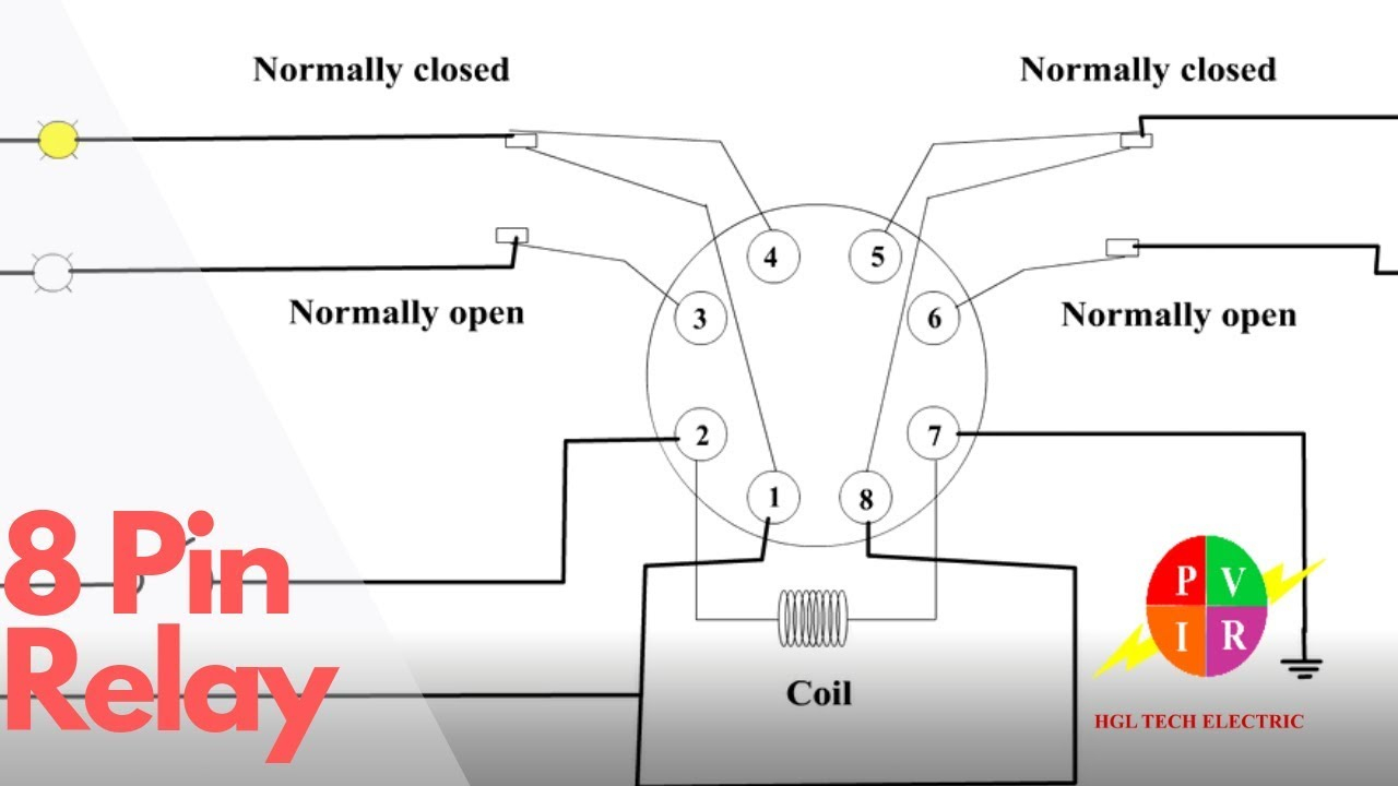
What is a wiring diagram? A wiring diagram is a simple visual representation of the physical connections and physical layout of an electrical system or circuit. It shows how the electrical wires are interconnected and can also show where fixtures and components may be. Intermediate relay wiring diagram 5 and 6 are a pair of common terminals, 1 and 2 are a pair of normally closed contacts, and 3 and 4 are a pair of normally open contacts.
Wiring compressor diagram potential motor starting relay hermetic schematic universal refrigeration relays motors electric components air drives bearings devices solid. Air condition compressor potential. You can easily be able to wire a relay by your end without any confusion. We are going to strip the insulation of the single horn relay wiring. An example of a wiring diagram for a motor controller is shown in figure 1. Note that symbols are discussed in detail later). Dashed lines indicate a single purchased component. This system uses 3 phase ac power (l1, l2 and l3) connected to the terminals. The three phases are then connected to a power interrupter.
120 Volt Relay Wiring Diagram Download

Gallery 5 Prong Relay Wiring Diagram Fresh 4 Pin Electrical Outlet - 5 Prong Relay Wiring

Best Relay Wiring Diagram 5 Pin Wiring Diagram Bosch 5 Pin Relay | Electrical diagram

Relay Wiring Diagram 5 Pin Stylesync Me Fair - blurts.me | Automotive electrical, Automotive

Automotive Wiring Relays Diagram Most Automotive, Relay Wiring Diagram, Auto Electrical Wiring

5-Pin Relay and Socket Harness | MGI SpeedWare

Basic Relay Connections | Electrical diagram, Automotive mechanic, Automotive repair

Best Relay Wiring Diagram 5 Pin Wiring | Electrical circuit diagram, Circuit diagram

8 Pin Relay Wiring Diagram | Wiring Diagram

12v Relay Diagram

